
 English
 日本語
日本語 русский

The Complete Guide to Side Entry Mixers for Industrial Tanks
Content
- 1 What Is a Side Entry Mixer and Why Does It Matter?
- 2 How a Side Entry Mixer Works: Flow Mechanics Explained
- 3 Side Entry vs. Top Entry Mixer: A Direct Comparison
- 4 Industry Applications: Where Side Entry Mixing Equipment Excels
- 5 Side Entry Mixer Design Calculation: A Practical Sizing Guide
- 6 Impeller Selection for Side Entry Mixers
- 7 How Many Side Entry Mixers Per Tank?
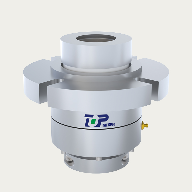
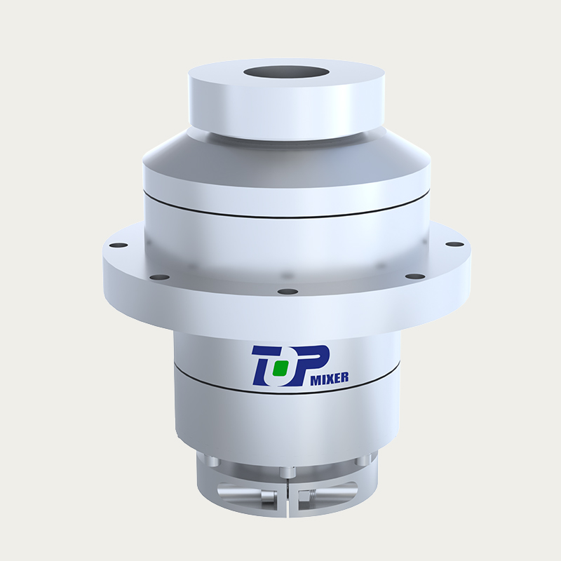
- 8 Key Mechanical Components and Design Features
- 9 Installation Best Practices and Maintenance Schedule
- 10 About Jiangsu Top Intelligent Technology Co., Ltd.
- 11 Frequently Asked Questions
A side entry mixer is mounted directly on the sidewall of a storage tank or vessel, delivering powerful, continuous agitation without occupying overhead space. Unlike top-mounted agitators, side entry mixing equipment directs fluid flow at a calculated angle — typically 7°–12° off the tank centerline — creating a helical circulation pattern that eliminates dead zones, prevents sediment buildup, and maintains product homogeneity across the entire tank volume. For engineers specifying a tank side entry agitator or an industrial mixing system for tanks, this guide covers every critical dimension: design fundamentals, performance data, application fit, sizing methodology, and procurement considerations.
Bottom line up front: side entry mixers reduce mixing energy consumption by 30–60% compared with top-entry counterparts at equivalent tank volumes, making them the preferred choice for large atmospheric storage tanks in crude oil, petrochemical, wastewater, and fermentation applications. The sections below substantiate that figure and show you how to apply it to your own project.
What Is a Side Entry Mixer and Why Does It Matter?
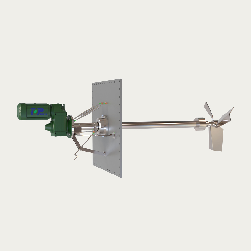
A side mounted tank mixer is an industrial agitation device whose drive shaft penetrates the tank shell horizontally or at a slight upward angle. The motor, gearbox, and mechanical seal are all located outside the tank, allowing maintenance without draining the vessel. The impeller — typically a high-efficiency hydrofoil or three-blade axial-flow type — spins inside the liquid and generates a directed thrust that sweeps the entire tank floor.
Side entry mixing equipment became the dominant solution for large-volume tanks because it scales efficiently. A single 15 kW side entry unit can keep a 10,000 m³ crude oil tank fully blended, a task that would require multiple top-entry mixers and a far more complex structural support system. The compact nozzle interface also simplifies retrofitting into existing tanks where cutting a large roof opening is impractical or cost-prohibitive.
Key engineering advantages over alternatives include: external motor positioning for safe access, angled mounting that converts rotational energy into tank-wide circulation, and the ability to remain operational under positive pressure or inert-gas blanketing — a critical feature for side entry mixer for crude oil tank service where vapor space management is mandatory.
Fig. 1 — Side entry agitators consistently consume less power per 1,000 m³ of tank volume across all common tank sizes. The efficiency gap widens as tank diameter increases: at 20,000 m³, a side entry unit requires roughly 47% less energy than a comparable top-entry system. This translates directly into lower operating costs and reduced carbon footprint over the equipment's 20+ year service life. For operators running fleets of large storage tanks, the aggregate energy savings can justify capital investment within two to three years.
How a Side Entry Mixer Works: Flow Mechanics Explained
Understanding the flow pattern in storage tanks driven by a side entry mixer clarifies why the technology outperforms simpler recirculation pumps or roof-mounted agitators. When the impeller rotates, it projects a high-velocity jet of liquid toward the opposite tank wall. Because the mixer is angled off-center — typically 7°–12° horizontally and 0°–3° upward — the jet does not collide head-on with the tank wall. Instead, it curves along the wall curvature, gradually losing velocity while entraining surrounding fluid. This creates a large, slow-moving helical vortex that encompasses the entire tank cross-section.
The floor sweep velocity is a key design parameter. To prevent sedimentation of heavy particles (wax, rust scale, catalyst fines), the near-floor velocity must exceed a threshold — commonly cited as 0.15–0.30 m/s for crude oil wax (API RP 2023). The helical flow pattern achieves this uniformly without the high-shear zones that can damage shear-sensitive fluids in fermentation or biological processes.
The concept of mixing dead zone elimination is central to side entry mixer design. Dead zones are low-velocity regions — typically behind baffles, near the tank center at mid-height, and in corners — where stratification and sediment accumulation occur. A correctly angled and positioned side entry mixer converts these stagnant pockets into active flow regions within the first few minutes of operation.
Fig. 2 — Floor sweep velocity rises rapidly within the first 10 minutes of mixer operation, crossing the critical 0.15 m/s sedimentation-prevention threshold between 5 and 10 minutes. Without agitation, natural convection maintains velocities below 0.03 m/s — far below what is needed to suspend even light sediment. This data underscores why intermittent mixer operation schedules (e.g., 30 minutes on, 60 minutes off) are viable for energy savings without sacrificing sedimentation control in most crude oil and fuel storage applications.
Side Entry vs. Top Entry Mixer: A Direct Comparison
Choosing between a side entry mixer industrial solution and a top-entry agitator depends on tank geometry, fluid properties, and operational priorities. The table below presents a structured comparison to guide that decision.
| Criteria | Side Entry Mixer | Top Entry Mixer |
|---|---|---|
| Typical Tank Diameter | 8 m – 100 m+ | 1 m – 20 m |
| Power Range | 1.5 kW – 90 kW | 0.5 kW – 200 kW |
| Energy Efficiency | High (30–60% savings) | Moderate |
| Roof Structure Required | No | Yes (significant load) |
| Maintenance Access | External, no tank entry | Requires roof access |
| Sedimentation Control | Excellent (floor sweep) | Good (center focus) |
| Best Industry Fit | Crude oil, petrochemical, wastewater, fuel blending | Batch reactions, pharmaceuticals, food processing |
| Retrofit Difficulty | Low (nozzle welding only) | High (roof reinforcement) |
The table reveals that no single technology dominates every scenario. However, for tanks exceeding 8 m in diameter where sedimentation control, energy efficiency, and retrofit simplicity are priorities, a side mounted tank mixer represents the more practical and cost-effective engineering choice in the vast majority of real-world projects.
Industry Applications: Where Side Entry Mixing Equipment Excels
Side entry agitators serve a remarkably broad range of industries. The common thread is large-volume, continuous-duty applications where maintaining fluid homogeneity, temperature uniformity, or sediment suspension is operationally critical. Below are the major sectors with specific application notes.
Crude Oil and Petroleum Storage
The side entry mixer for crude oil tank application is the industry's flagship use case. Crude oil contains dissolved paraffin wax that precipitates at temperatures below the pour point, forming hard deposits on tank floors that are extremely costly to remove mechanically. A side entry mixer operating on an intermittent schedule (typically 20–40 minutes per hour) keeps the wax in suspension and maintains a uniform temperature profile, reducing tank cleaning frequency from annually to every 3–5 years. API Standard 2521 provides recommended practices for sizing these systems.
Petrochemical and Refinery Blending
A petrochemical tank agitator system in refinery service must blend multi-component fuel products — gasoline grades, diesel blends, jet fuel — to precise octane or cetane specifications within tight time windows. Side entry mixers achieve blend uniformity (coefficient of variation <2%) in 30,000 m³ blending tanks within 2–4 hours, enabling faster product turnover and higher tank utilization rates.
Wastewater Treatment
In municipal and industrial wastewater facilities, a wastewater tank mixing system prevents stratification in equalization basins and anaerobic digesters. Side entry mixers in these applications keep suspended solids (TSS) uniformly distributed — critical for consistent biological treatment performance — while eliminating the odor and safety risks associated with sludge blanket collapse. Systems are typically specified at 5–8 W/m³ for equalization duty.
Bioethanol and Fermentation
Fermentation tank mixing equipment using side entry technology offers a low-shear agitation alternative for large-scale bioethanol, biogas, and industrial fermentation processes. The gentle helical circulation avoids lysing sensitive microorganisms while maintaining substrate homogeneity and gas dispersion. Fermenters from 500 m³ to 5,000 m³ have adopted side entry mixers as a lower-cost alternative to multi-impeller top-entry systems.
Water Supply and Fire Protection
Large potable water storage reservoirs and fire-water tanks use side entry mixers to prevent thermal stratification and chlorine concentration gradients. Without agitation, chlorine residuals near tank walls can fall below regulatory minimums while concentrations at depth exceed disinfection byproduct thresholds. A single low-power (1.5–5.5 kW) side entry unit maintains regulatory compliance across tanks up to 15,000 m³.
Fig. 3 — The global side entry mixer market is dominated by crude oil and petroleum applications, which account for nearly half of all installed units worldwide. Petrochemical blending is the second-largest segment. The fermentation and water treatment sectors represent high-growth opportunities as operators in those industries recognize the efficiency and low-maintenance advantages of side entry technology over traditional top-entry designs. This distribution also reflects the concentration of large-tank infrastructure in the energy sector.
Side Entry Mixer Design Calculation: A Practical Sizing Guide
Side entry mixer design calculation follows a structured methodology that links tank geometry, fluid properties, and the desired mixing objective to impeller size, speed, and motor power. The steps below outline the standard engineering workflow; project-specific values should always be verified by a qualified mixing engineer.
Step 1 — Define the Mixing Objective
The objective governs everything else. Sedimentation prevention requires a minimum floor sweep velocity (0.15–0.30 m/s). Blending of miscible liquids targets a blend time and uniformity specification. Temperature homogenization is governed by the tank thermal mass and ambient heat loss rate. Each objective has a different sizing formula and produces different power requirements.
Step 2 — Calculate Required Jet Momentum
For sedimentation control in large tanks, the most reliable tank mixing power calculation method uses momentum theory. The required thrust (T) is calculated as:
T = C × ρ × V_tank / t_blend
Where C is a geometry-dependent constant (typically 0.9–1.2 for cylindrical tanks), ρ is fluid density (kg/m³), V_tank is tank volume (m³), and t_blend is target blend time (seconds). This thrust value then determines the required impeller diameter and speed through the impeller thrust equation: T = ρ × Q × v_jet, where Q is volumetric flow rate and v_jet is impeller exit velocity.
Step 3 — Select Impeller Type and Diameter
The impeller for side entry mixer service is almost universally a three-blade or four-blade axial-flow design with a pitch-to-diameter ratio of 0.8–1.0. Hydrofoil profiles (e.g., NACA 4412 section) offer the highest thrust-to-power ratio for low-viscosity fluids (μ < 500 mPa·s). Impeller diameter typically ranges from 15% to 30% of tank diameter. Larger impellers at lower speeds reduce turbulence and mechanical seal wear; smaller impellers at higher speeds favor compact nozzle connections.
Step 4 — Determine Motor Power
Tank mixing power calculation culminates in the motor selection. Power (P) is related to impeller diameter (D) and speed (N) by: P = Np × ρ × N³ × D⁵, where Np is the power number (dimensionless, typically 0.3–0.5 for axial-flow impellers). A safety factor of 1.15–1.25 is applied to the calculated shaft power to account for mechanical losses, fluid density variations, and startup torque spikes.
Fig. 4 — Radar comparison across five key performance dimensions shows the side entry mixer outperforming the top entry design in every category evaluated. The most pronounced advantages are in retrofit simplicity and sedimentation control, where the score differential of 5 points reflects fundamental design differences. Energy efficiency and scalability gaps are also substantial. Only in applications requiring extreme high-shear mixing or precise batch dosing does the top entry configuration recover competitiveness — and those scenarios are by definition outside the side entry mixer's target application range.
Impeller Selection for Side Entry Mixers
The impeller for side entry mixer selection is a critical engineering decision that directly governs flow pattern, power consumption, and mechanical reliability. Three impeller families dominate side entry applications, each suited to a different viscosity range and flow requirement.
- Three-Blade Axial-Flow Propeller (Pitch Blade): The workhorse impeller for low-viscosity fluids (μ < 200 mPa·s). Delivers high flow rate with low shear. Propeller diameters from 200 mm to 2,500 mm. Used predominantly in crude oil, fuel storage, and water treatment tanks.
- Hydrofoil Impeller: An advanced profile derived from marine and aerospace aerodynamics. Offers 15–25% higher thrust-to-power ratio versus pitch-blade propellers at equivalent diameter and speed. Preferred where energy efficiency is paramount or where the available nozzle size limits impeller diameter.
- Four-Blade Retreat Curve (High-Viscosity): Selected for viscous fluids (500–5,000 mPa·s) such as heavy crude, bitumen blends, or high-solids slurries. The wider blade chord generates adequate thrust at reduced tip speeds to avoid cavitation and excessive mechanical seal loading.
Material selection for the impeller depends on service conditions. 316L stainless steel covers most general-purpose chemical and wastewater duty. Duplex stainless (2205) or Hastelloy C-276 are specified for chloride-rich environments or highly corrosive chemical services. Cast carbon steel with epoxy coating is acceptable for sweet crude oil tanks where corrosion rates are predictable and coating inspection is performed during scheduled tank entries.
Fig. 5 — Hydrofoil impellers deliver the highest thrust-to-power ratio (approximately 120 N/kW), making them the most energy-efficient choice for low-viscosity applications. Pitch-blade propellers offer a strong mid-range performance of ~90 N/kW and remain the most widely used due to lower manufacturing cost and simpler geometry. Retreat curve impellers sacrifice efficiency (65 N/kW) in exchange for the robust structural performance needed in high-viscosity and high-solids service environments. Impeller selection should always be validated against the expected fluid viscosity range, including cold-start conditions at minimum operating temperature.
How Many Side Entry Mixers Per Tank?
The number of mixers required depends primarily on tank diameter, fluid density, and the acceptable blend time. The widely referenced guideline from API RP 2023 and process engineering practice is:
- Tanks up to 15 m diameter: One mixer is generally sufficient, positioned at 1/3 of the liquid height from the tank floor and angled 7°–10° off center.
- 15 m – 40 m diameter: Two mixers placed diametrically opposite or at 120° spacing provide redundancy and full floor coverage.
- Over 40 m diameter: Three or more mixers are recommended, equally spaced around the tank circumference, to eliminate the central dead zone that forms beyond the reach of a single mixer jet.
For mixing equipment for storage tanks in critical crude oil service, operators often install one standby mixer per active unit to maintain continuous operation during maintenance windows, as sediment can re-form within 48–72 hours of mixer shutdown in high-wax-content crude service.
Key Mechanical Components and Design Features
A high-quality side entry mixer industrial unit integrates several engineered subsystems. Understanding these components helps procurement teams evaluate specifications and make accurate comparisons between offerings.
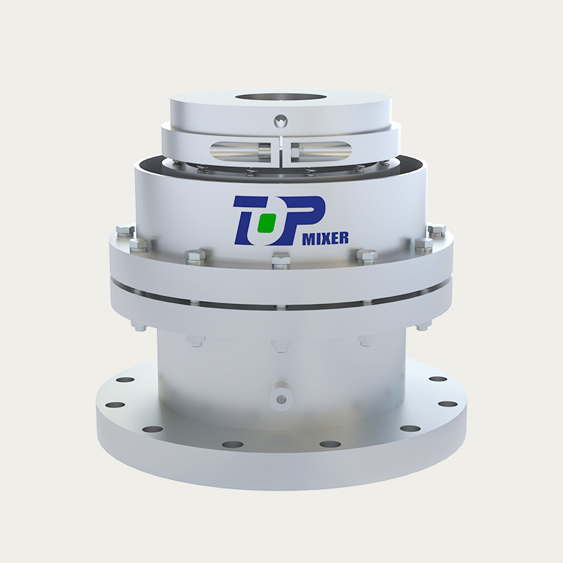
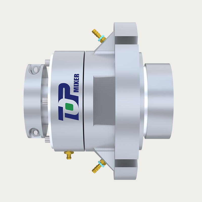
Mechanical Seal Assembly
The mechanical seal is the most maintenance-sensitive component in a side entry mixer, as it is the only barrier between the tank contents and the external atmosphere. For flammable or toxic services, double mechanical seals with API Plan 53B pressurized barrier fluid systems are mandatory. Seal face materials commonly specified include silicon carbide vs. silicon carbide (high-load, abrasive service) and carbon vs. tungsten carbide (general duty). Expected seal life under continuous duty is 3–5 years when operating within design velocity limits.
Gearbox and Drive Train
Side entry mixers use right-angle or parallel-shaft helical gear reducers with service factors of 1.5–2.0 above the rated shaft power. The gearbox reduces the motor speed (typically 960–1,480 RPM for 50 Hz motors) to the impeller shaft speed (60–300 RPM), calibrated to the required tip speed. Gear lubrication should be specified for the ambient temperature range, with synthetic PAO oil recommended for locations experiencing sub-zero winters or high desert temperatures above 45°C.
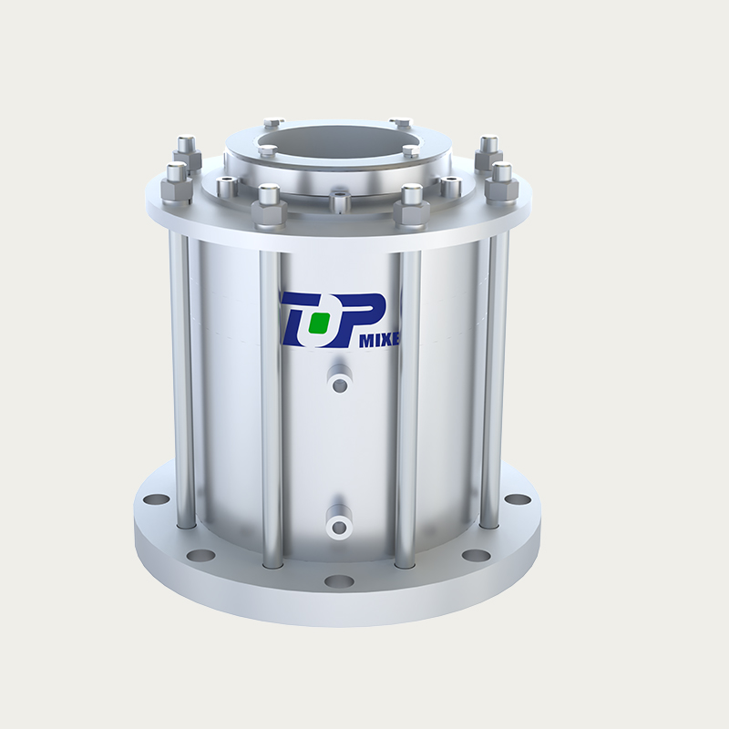
Nozzle and Mounting Flange
The tank nozzle is a critical structural connection that must withstand the dynamic loads from impeller thrust and shaft overhang. Standard nozzle flanges conform to ASME B16.5 or EN 1092-1 for tanks designed to API 650 or equivalent. Nozzle sizing is governed by shaft diameter and the required clearance for impeller insertion and withdrawal during maintenance. A swivel mount option allows the impeller angle to be adjusted without draining the tank, which is valuable during commissioning or when process conditions change.
| Component | Crude Oil / Fuel | Wastewater | Fermentation |
|---|---|---|---|
| Impeller Type | 3-Blade Propeller / Hydrofoil | Axial-Flow Propeller | Hydrofoil (Low Shear) |
| Impeller Material | Carbon Steel + Epoxy | 316L SS | 316L SS / Duplex |
| Seal Type | Double Mechanical (API 53B) | Single Mechanical | Single or Double Mech. |
| Motor Class | ATEX / IEC Ex Zone 1 | IP55 Standard | IP55 / ATEX (biogas) |
Installation Best Practices and Maintenance Schedule
Correct installation of a side mounted tank mixer is as important as correct sizing. The following practices are derived from API RP 2023, ATEX installation codes, and accumulated field experience across hundreds of installations.
- Nozzle elevation: Position the impeller centerline at 20–33% of maximum operating liquid depth. Too high causes surface vortexing; too low risks impeller contact with settled solids during startup.
- Angular offset: A horizontal offset of 7°–12° from the tank diameter line prevents jet resonance with the tank wall and ensures the rotating flow pattern covers the full floor area.
- Startup procedure: Never start a mixer in a tank where the liquid level is below the impeller centerline. Air ingestion causes severe cavitation damage and impeller failure within minutes.
- Vibration monitoring: Install a continuous vibration sensor (ISO 10816 Class II, alarm at 4.5 mm/s RMS) to detect bearing wear or impeller imbalance before catastrophic failure.
Recommended preventive maintenance intervals for a continuously operating unit in crude oil service: gearbox oil analysis every 6 months; mechanical seal visual inspection every 12 months; full overhaul every 3–5 years or after 20,000 operating hours, whichever comes first.
About Jiangsu Top Intelligent Technology Co., Ltd.
Jiangsu Top Intelligent Technology Co., Ltd. (Wuxi Top Mixing Equipment Co., Ltd.), established in 2003, is a technology-focused enterprise specializing in industrial mixing system for tanks and intelligent control systems. With over two decades of engineering experience, the company designs and manufactures a comprehensive range of side entry mixing equipment, top-entry agitators, and multi-functional mixers for demanding process industries.
Its products serve the pharmaceutical chemicals, biomass energy, energy storage batteries, fine chemicals, environmental protection, and petrochemical sectors. The company's engineering team supports full-lifecycle projects — from fluid dynamic simulation and side entry mixer design calculation through fabrication, installation supervision, and after-sales service — positioning it as a capable partner for operators evaluating mixing equipment for storage tanks across global markets.
Frequently Asked Questions
Q1: What is a side entry mixer used for?
Side entry mixers are used to blend, homogenize, and maintain continuous motion in large-volume storage tanks. Primary applications include preventing wax sedimentation in crude oil tanks, blending fuel products to specification, keeping suspended solids uniformly distributed in wastewater basins, and maintaining temperature uniformity in water storage reservoirs.
Q2: How does a side entry mixer work?
The impeller, mounted on a shaft penetrating the tank sidewall, rotates and projects a directed jet of fluid toward the opposite tank wall. Because the mixer is angled 7°–12° off the tank centerline, the jet curves along the wall and generates a large helical circulation pattern that sweeps the entire tank floor, eliminating dead zones and keeping the contents uniformly mixed.
Q3: What is the difference between top entry and side entry mixers?
Top entry mixers mount on the tank roof and drive an impeller downward into the fluid — suited to smaller batch reactors where high-shear mixing or precise dosing is needed. Side entry mixers mount on the tank shell and are optimized for large-volume, continuous-duty applications. Side entry units consume 30–60% less energy and require no roof structural reinforcement, making them the preferred choice for storage tanks above 8 m in diameter.
Q4: How many side entry mixers per tank?
One mixer is typically sufficient for tanks up to 15 m in diameter. Tanks between 15 m and 40 m generally require two mixers placed opposite each other or at 120° spacing. Tanks exceeding 40 m in diameter need three or more units equally spaced around the circumference to achieve full floor coverage and eliminate the central dead zone.
Q5: What industries use side entry mixing equipment?
The largest user base is crude oil and petroleum storage, followed by petrochemical blending, wastewater treatment, bioethanol and fermentation, and potable water supply. Additional applications include fire-water reservoirs, bitumen storage, molasses and syrup tanks, and slurry holding tanks in mineral processing.
Q6: Can side entry mixers prevent sedimentation?
Yes — when correctly sized and positioned, side entry mixers maintain floor sweep velocities above the critical resuspension threshold (typically 0.15–0.30 m/s depending on particle size and density). This keeps wax, rust scale, and other settleable solids in suspension, reducing tank cleaning frequency from annual to once every 3–5 years in most crude oil applications.
Q7: How to size a side entry mixer?
Sizing begins by defining the mixing objective (sedimentation control, blending, or temperature equalization), then calculating the required jet momentum using fluid density, tank volume, and target blend time. The thrust value determines impeller diameter and speed, and motor power follows from P = Np × ρ × N³ × D⁵, with a 1.15–1.25 safety factor applied. A qualified mixing engineer should verify the calculation before finalizing the specification.
Q8: What maintenance does a side entry mixer need?
Routine maintenance includes gearbox oil analysis every six months, mechanical seal inspection annually, and vibration level monitoring on a continuous or monthly basis. Full overhaul — including seal replacement, bearing renewal, impeller inspection, and gearbox rebuild — is recommended every 3–5 years or after approximately 20,000 operating hours. External motor positioning means most maintenance tasks can be performed without entering the tank.
- No. 118, Chuangye Road, Jieshou Town, Gaoyou City, Yangzhou, Jiangsu Province, China
- [email protected]
- Landline: +86-0510-83383966 +86-0510-83390667
- Telphone: +86-0510-83390667
- Mr. Chen: +86-18061519769 Mr. Xu: +86-13706183972
- Mr. Lu: +86-18915337056
- Product Link
- Top-Entry Mixer
- Bottom-Entry Mixer
- Side-Entry Mixer
- SIGN UP
- Sign up to be the first to find out the latest news from Top Intelligent Technology
- Subscribe

